
Triangular Trusses
Have you ever noticed that many engineering structures (bridges, beams, buildings, towers, trusses …) are constructed using triangles. Why is this?
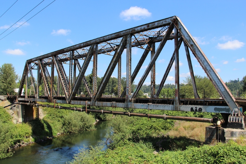 image: cmh2315fl
|
The simple answer is that triangles are stable. A triangle has three sides and, if these are fixed in length, there is only one configuration they can be in. There is no flexibility or freedom. (Another way to think of this is that the angle of each corner is held rigidly in place by the side opposite it). |
 |
 |
A quadrilateral (or higher sided shape) has more degrees of freedom. Without changing any of the lengths of the sides the shape can be skewed/squashed or deformed. |
Triangles help keep structures rigid.
Also, in an effort to reduce weight, make more efficient use of material, and to reduce cross sectional area for wind resistance, many stressed structures are not built from slabs of material, but instead are made of skeletons of trusses. Rectangular regions are subdivided into triangles.
 image: Scott Kublin
Toothpaste Box
Below is an example of a cross section of an open ended rectangular tube. It is very easy to squash and skew this entity. To make it more stable, the rectangle can be subdivided into two triangles by the addition of a cross-brace connecting two opposite corners.
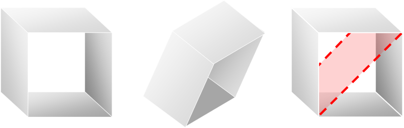
It's is this principle that engineers employ when bracing structures.
Combinations of these building blocks can be combined to make larger structures.
How much is enough?
 |
A theoretical questions can arise: How much bracing is enough? Obviously, sufficient bracing wants to be added to a structure so that it does not warp or skew under load, but does every rectangle need to be braced? |
|
For instance, in the structure to the right, which is made up of 2x2 squares, if any three of the four squares are braced (it does not matter which), then the fourth is automatically rigid because the other three are fixed. If three squares are already braced, then the structure is rigid before the addition of the fourth square. Bracing the fourth square is redundant. |
 |
More complex
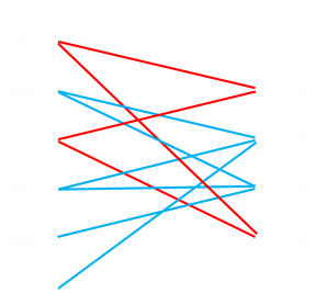
The above example was a trivial, but what happens if our structure gets more complex? Are either of these two sparsely braced structures rigid? They both have ten cross braces.
As it happens the structure on the left is rigid, but the one on the right is not. How would we go about determining this? We could build them out of pin-jointed children's construction toys and try to distort them, but is there a mathematical way?
Let's think about this for a second or two. When a rectangle is deformed, because the opposite sides are of equal length, what happens is that opposites sides remain parallel. The rectangle skews.
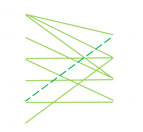
Because of we know that rectangles stay as rectangles or skew to parallelograms we know that all vertical connections in any row must remain parallel (example highlighted green below), and all horizontal connections in the same column also remain parallel (highlighted yellow).
We know also that any rectangle that is braced, remains as a rectangle (highlighted red).
You can verify these three facts from the diagrams above.
Where there is a rectangle in a row, column then everything in that those row and columns is parallel and perpendicular to that rectangle respectively.
To have a rigid structure, the vertical connections in any row need to be perpendicular to the horizontal connections in every column
Graph theory
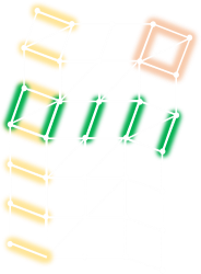
If we draw a graph showing the grids that are braced, we get the following diagrams. In these diagrams, each node on the left depicts the rows, and each node on the right the columns. A link is drawn for every brace showing the row and column it is braced between. Here is the graph for our first example:
 |
 |
If there is some path connecting a row and column, then we know that the vertical connections and horizontal connections are parallel and perpendicular.
What this means is that if the graph is connected (there is a path between any pair of rows/column nodes), then the structure is rigid. This is the case for the graph for the left example structure; every row and column node is connected in some way with every other row and column node. Everything is parallel and perpendicular. The structure is rigid.
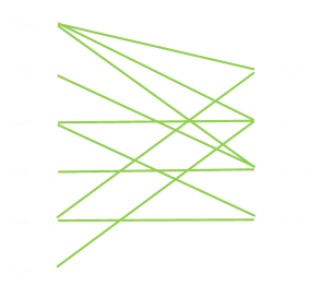
Example 2
The graph for the example structure on the right contains, in this case, two orphaned graphs. There are two distinct parts of the graph (shaded red and blue), and these are not connected. The structure is not rigid.
 |
 |
 |
There is no path (brace) connecting the two distinct graphs, so there is a degree of freedom.
It would be possible to make the structure rigid if a brace were added that connected these two graphs (or if one of the braces were changed). For instance, this structure could be made rigid by moving the brace in the last row to either the first of last column.
Redundancy
Similarly, we can see that the structure for our first example is over engineered. It's possible to remove a brace and still keep the structure rigid. For instance removing the brace marked below will still keep the structure rigid. (This isn't the only solution, can you see others?)
 |
 |
To ensure a structure is rigid, every row needs to be connected to every column through some path, no matter how convoluted. What the graph needs to be be is a spanning tree. If there are R rows and C columns in a grid, the the minimum number of links required to make a connected graph is R + C − 1. This is the minimum number of braces required on a grid to make it stable.
So, for our first example, once we've removed one of the redundant braces, there is no other optimization we can make. With six rows, and four columns, the minimum number of braces for a rigid structure is nine.
Push me, pull you
In real structures, sometimes the braces need to support tension forces (being pulled apart), and sometimes in compression (being squashed). Braces that support in tension are usually given the name TIES. Braces that support compression loads are typically called STRUTS.
Reality
In reality, engineers like redundancy. We never want to build a structure with a single point of failure. More bracing is used than needed so that even if something fails, our structure does not collapse.
Also, even with the best planning in the World, additional forces can be imposed on structures that were not designed for (Wind, unbalanced atypical loads, snow, heavy paint …) It's nice to have safety margins.
Plus, it looks nice! Is this not a thing of pure beauty?
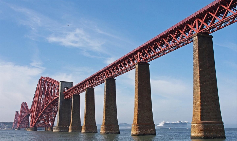 image: Vurnman
You can find a complete list of all the articles here. Click here to receive email alerts on new articles.
© 2009-2014 DataGenetics Privacy Policy